I’ve been working on something called Curve Grapher. It’s a webpage that renders graphs of math equations, like $z = sin(p x) cos(p y)$.
In the example above, the application realizes that $p$ isn’t a co-ordinate. It shows a slider which lets you change the value of $p$. Doing so updates the graph in real time!
This post is a high level overview of how this works. My first attempt at building it was too slow. I’ll talk about the current version which is much faster, and some of what I learned building it.
Also, this post is specifically about rendering explicit 3D equations (where the right hand side of depends only on $x$ and $y$). Curve Grapher also handles implicit 2D and 3D equations, like $sin(x) = cos(y) - sin(z)$. I hope to write more about that later.
High level approach
The high level API of THREE.js (and many graphics engines) is that you tell it to render a collection of triangles in 3D, and it does it. You position a triangle by telling THREE.js where each of its vertices are.
When a collection of triangles form something cohesive, like a graph, we call it a mesh.
My first approach to building a grapher was something like this THREE.js demo. In it, the author creates a mesh and - in Javascript - positions its vertices using the equation entered by the user. THREE.js has a nice wrapper for this called ParametricGeometry.
When the user changes the equation, you have to update the mesh’s vertex positions. To do this, the demo iterates over all vertices (in Javascript) and repositions them. It works well. But when I implemented it, moving the variable slider felt really jaggy. I wanted something faster.
This is the approach I ended up using:
- We create a scene with one mesh: a flat plane. Every vertex in the plane has a z-value of $0$. The x and y values range from $-10$ to $10$.
- When the user enters a new equation, we use it to generate a vertex shader that sets the $z$ position of each vertex in the plane. A vertex shader is a piece of code that runs on the GPU and positions vertices before they are rendered. Vertex shaders do their work largely in parallel. Setting vertex positions this way is really fast.
- Variables like $p$ in the example above are passed to the shader from Javascript using something called a uniform (I’ll say more about what that is later).
To illustrate how much faster this approach is, here’s a graph of how long it takes each method to prepare to render the equation $z = sin(x p) cos(y p)$ on a mesh with 40 000 vertices:

This is just one sample on my laptop. It’s hardly scientific, but it should still be convincing to you. $397ms$ is way too slow to feel interactive. The approach I talk about in this post is fast enough to make slider manipulation feel smooth.
Transforming user-input into shaders
WebGL Shaders are pieces of code written in a language called GLSL. Unlike Javascript code running on this webpage, they run on the GPU. In WebGL applications, the source code of a shader starts out as a string in Javascript. It’s passed to the GPU after you call the WebGL function gl.shaderSource with the source code as an argument.
Passing a new shader to WebGL is surprisingly fast. You can do it in the time between two frames of your computer screen being renderered. There are some exceptions to this (particularly on Windows) but that hasn’t been a problem for me in practice.
An example of a common vertex shader is below. Feel free to skim it. You don’t need to understand it in detail to read the rest of this post.
// These variables are passed to the shader
// from Javascript code. More on that below.
attribute vec3 position;
uniform mat4 modelViewMatrix;
uniform mat4 projectionMatrix;

void myVertexShader() {
  // We assign the final vertex position to
  // gl_Position. gl_Position is a magical
  // variable that you can think of as the
  // return value of this function.
  gl_Position = (
    projectionMatrix *
    modelViewMatrix *
    vec4(position, 1.)
  );
}
There are two things you need to know about this code.
The first is that this shader is “standard”. I feel bad saying that because it contains what I’m sure looks like complex hokey pokey. It’s standard in the sense that it’ll render vertices to your screen in the right place.
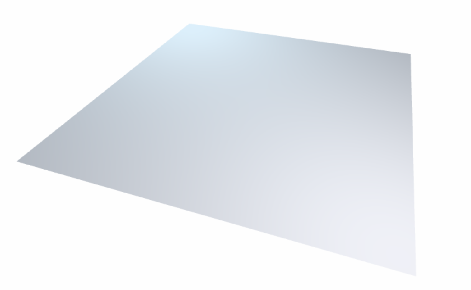
What do I mean by that? If I use it to render a flat plane from $(-10, -10)$ to $(10, 10)$, the rendered image will look like a flat plane from $(-10, -10)$ to $(10, 10)$. Like so…
The second important thing to notice is that it uses a variable declared as attribute vec3 position. Vertex shaders are run on the GPU in parallel. Each time you render, WebGL will invoke the function in the shader once for each vertex in your mesh. Each time it’s invoked, position will hold the position of the vertex being processed.
The attribute keyword before the declaration of position says that it was assigned to the triangle mesh by our Javascript code before the scene was rendered. Since we’re rendering a flat plane, position.z will always be $0$. position.x and position.y will range from $-10$ to $10$.
Let’s change this shader so that, instead of rendering a flat plane, it renders the graph of $z = sin(x p) cos(y p)$:
// These are the same as before.
attribute vec3 position;
uniform mat4 modelViewMatrix;
uniform mat4 projectionMatrix;

// This holds the user-defined value of the
// variable p
uniform float var_p;

vec3 userDefinedPosition() {
  float x = position.x;
  float y = position.y;
  return vec3(x, y, sin(x * var_p) * cos(y * var_p));
}

void myVertexShader() {
  gl_Position = (
    projectionMatrix *
    modelViewMatrix *
    vec4(userDefinedPosition(), 1.)
  );
}
Notice that this shader uses a function called userDefinedPosition() where the old shader used position.
userDefinedPosition() is a function that returns a vector like position except its z-value has been set according to the user’s equation.
You might have noticed that the shader uses a variable called var_p, declared with the keyword uniform. This means that it’s passed to the shader from Javascript. When you move a variable slider, we just change this uniform value instead of generating a new vertex shader.
Most of the shader above is boilerplate. These are the only parts that change when the user enters a new equation:
- uniform declarations of variables, like
uniform float var_p; - the expression for the z-value of each vertex, like
sin(x * var_p) * cos(y * var_p)
In practice, we could use a template string for most of our shader. Whenever the user enters a new equation, we generate the two things above and splice them in.
If it seems weird to you that we’re generating code while the application is running, you’re not alone. But it works! WebGL shaders can be defined at run-time and you can pass new ones to WebGL pretty much any time you like.
Parsing
A parser is a piece of code that takes some other piece of code as input and spits out something called an Abstract Syntax Tree (AST). Using our example above, it would take $z = sin(x p) cos(y p)$ and turn it into this:

Each node in this AST represents one of the following…
- a variable like $x$, $y$, or $p$
- an operator like $+$, $*$ or $=$
- a function call ($\sin$, $\cos$)
This data structure is useful to us because it removes language specific details from the equation. You could inspect the tree above and write Java that represents it, or C++, or python, etc. In our case, we’re going to use the AST to generate GLSL.
In code, the y * p part of this tree (bottom right) is represented by a Javascript object like this…
const node = {
  // Each node has a type.
  type: 'TIMES',

  // children is an array of
  // nodes.
  children: [{
    type: 'VARIABLE',
    name: 'y',
    children: [],
  }, {
    type: 'VARIABLE',
    name: 'p',
    children: [],
  }]
}
Each node of the tree has a type and a list of children. Operator nodes like TIMES have a list of two children. VARIABLE nodes have names like $y$ and $p$ and have no children.
There are many good open-source equation parsers online. But I’ve felt for a while that parsing and compiler technology is out of reach. I decided to build my own so I could stop feeling that way.
My parser uses a technique called Pratt Parsing. If you’re interested in learning more about it, I recommend this excellent article. I also found it helpful to read the source code for GLSLX, which uses a Pratt Parser to parse expressions in GLSL code.
My parser gave me a way to turn the user’s equation into an AST. The next step is turning an AST into GLSL.
GLSL generation
Given an AST, we want to…
- Find variables that aren’t co-ordinates, so that we can generate uniform declarations for them (like
uniform float var_p;). - Generate a GLSL expression for the user’s equation, like
sin(x * var_p) * cos(y * var_p).
The first task is solved by looking at each node in your AST and keeping track of any nodes of type VARIABLE whose name isn’t x or y.
To solve the second task, we recursively walk through the tree and generate GLSL for each subtree. Here’s a really simplified example of the real function that does this:
function toGLSL(node) {
  if (node.type === 'VARIABLE') {
    if (node.name === 'x' || node.name === 'y') {
      return node.name;
    }

    // This is a variable like p
    return 'var_' + node.name;

  } else if (node.type === 'FUNCTION_CALL') {
    return (
      node.name +
      // children are arguments to the function
      '(' + node.children.map(toGLSL).join(', ') + ')'
    );

  } else if (node.type === 'PLUS') {
    return (
      toGLSL(node.children[0]) +
      ' + ' +
      toGLSL(node.children[1])
    );

  } else if (...) {
    ...

  } ...

}
This function takes in an AST and returns code like sin(x * var_p) * cos(y * var_p).
And that’s it. We stuff this into a template string to generate the desired vertex shader!
Conclusion
I this article, I showed you how to build real-time manipulable graphs by using a vertex shader to position mesh vertices on the GPU. The technique of generating vertex shaders at run-time is not new. But it’s powerful and something I plan to explore more deeply.
Hopefully this was interesting to you! If you have thoughts or comments, let me know below. Or, if you’re interested in more posts like this one, follow me on Twitter!
Here’s one last Graph I think is cool :-)
